Saturday, 24 December 2011

Merry Christmas!

We would like to wish everyone a Merry Christmas and Happy New Year!


Tuesday, 29 November 2011

FLL 2011 Food Factor Challenge


FIRST LEGO League (FLL) 2011 Food Factor Challenge is confirmed!


Note that FLL 2011 is traditionally held in USA first before Malaysia, and not held simultaneously worldwide for some reason. The challenge and topic remain the same for other countries worldwide.


Here is the Food Factor Teaser from the website that describe the challenge:

Can FIRST® LEGO® League teams improve the quality of food by finding ways to prevent food contamination?   In the 2011 Food Factor Challenge, over 200,000 9-16 year olds from over 55 countries will explore the topic of food safety and examine the possible points of contamination our food encounters – from exposure to insects and creatures, to unsterile processing and transportation, to unsanitary preparation and storage – then find ways to prevent or combat these contaminates.  In the Food Factor Challenge, teams will build, test, and program an autonomous robot using LEGO® MINDSTORMS® NXT to solve a set of Food Safety missions as well as research, develop, and share their innovative food safety solutions.  Throughout their experience, teams will operate under FLL’s signature set of Core Values.

We will be coaching two school teams for this challenge: LEGO Logic from Sekolah Seri Cahaya and Light Warriors from Sekolah Seri Suria. We wish them best of luck!

Friday, 4 November 2011

LEGO in Google NYC


Google NYC is Google's second largest office nestled among the towering skyscrapers of Manhattan. It is host to 2,500 employees, the second-largest number of Google engineers.

Google NYC is a place full of classic tech and LEGO whimsy. One entire wall in the office is devoted to LEGO art and LEGO creation. It was a struggle not to stop, stay and play.


Source: Mashable (link)

Saturday, 29 October 2011

LEGO Man may be released from custody


The 45.5kg, 2.5-metre-tall mysterious Lego man that was found on a Florida beach in U.S. may soon be sprung from a holding room.

Sarasota County Sheriff Tom Knight said the Lego-man could be freed from the shed where he's been kept for two days.

The giant Lego appeared on Siesta Key beach Tuesday morning.

"No Real Than You Are" was written on its shirt, along with "Ego Leonard" and the number 8.

Local newspapers report the name "Ego Leonard" is the name of a Netherlands artist, but it was not immediately clear who was behind the work.

The story of the Lego man has gotten worldwide attention.

Knight says the Lego man is being well kept and hopes the giant fiberglass man can be placed on display somewhere in the community.


Source: The Star (link)

Friday, 28 October 2011

Giant LEGO man washes ashore on Florida beach


Police in Florida have been left baffled after an 8ft tall LEGO man turned up on a beach.

Weighing 100lb, the giant LEGO man appeared on Siesta Key beach on Tuesday morning.

Bearing the cryptic message "No Real Than You Are" across the shirt, the words “Ego Leonard” were also visible of the outsized toy replica.
  
Ego Leonard is the name of a Dutch artist, but it is unclear as to whether Leonard is behind the toy stunt or if it is the work of an imitator.

LEGOLAND officials said the LEGO man was a counterfeit and is not endorsed by the company.

The mysterious plaything will remain in the protective custody of the Sarasota County Sheriff's Office until it is claimed.

A similarly gigantic LEGO man was washed up on Brighton beach in October 2008. (link)


A giant, smiling Lego man was fished out of the sea in the Dutch resort of Zandvoort in 2008

No one knew at that time where the colourful model, with Dutch writing on, came from either.

One resident said: "It must have fallen off a boat. The children love it."


Source: Mirror UK (link)

Tuesday, 11 October 2011

Ping Pong Robot made in China

A robot hits back a ball at Zhejiang University in Hangzhou, east China's Zhejiang Province, Oct. 9, 2011. 

Human-like robots developed by Zhejiang University in East China made debut on Sunday. The two robots as shown can capture the track of the ball by a camera installed inside before making reactions. The robots, 160 cm tall and weighing 55 kilograms each, took the university four years to develop. The university also aims to develop robots that can do housework.

The robots are able to track the movements of a table tennis ball and play back through a motion control system equipped with a built-in camera and an intelligence processing unit.

A robot plays pingpong with a visiting journalist at Zhejiang University.


Reference: XinHuaNet (link)

Tuesday, 4 October 2011

Ford Explorer in LEGO!

Fancy a unique bright red Ford Explorer SUV at half of the usual weight?


Ford Motor Co. and the LEGOLAND Florida theme park has formed a partnership with unveiling of a full-scale Explorer replication with LEGO bricks. The bright red LEGOLAND Florida edition Explorer will be on display at the new 150-acre LEGOLAND them park in Winter Haven, near Orlando.

The LEGO Explorer’s debut took place at the car maker’s Chicago assembly plant, which normally turns out real Explorers.

Crafted by 22 Ford employees, the Lego Explorer is made up of 382,858 LEGO bricks. It took 2,500 hours (about three and a half months) to complete. The structure weighs 1,203 kg and is supported by a 348 kg interior aluminium base.


LEGOLAND Florida, which opens Oct. 15, is designed for kids from the age of 2 to 12 and has more than 50 family-oriented rides, shows and other attractions. The park has exhibits that use more than 50 million LEGO bricks and is divided into 10 zones with different themes.


In 2004, a life-sized LEGO replica of a Volvo XC90 was built, also for a LEGOLAND in California.


Wednesday, 21 September 2011

I won RobotC 3.0 Licence giveaway!

I never win anything in my life... probably because I dont join anything :p

Anyway, today look what I won?


Haha... fine fine... it is a 1 in 3 chance in winning!

Eric


Monday, 19 September 2011

Starcraft 2 Seige Tank


It is too awesome not to blog this...

RobotC 3.0 is out

I have tried and played with RobotC 2.0.

It was simple to use as I do have a programming background. But I didn't do much with it since it is not NRC or FLL legal.


Now they have just released a new version, the RobotC 3.0.


Read a V2 -> V3 log on all the improvements (link to botbench pdf)


What I found most interesteding is the new Virtual Robots World (VRW) module look interesting, allowing users to program and simulate without actually needing a physical NXT robot. This could be great for students to practice programming at the comfort of their home.... or for those who needs a little more time at their own pace.

However the new RobotC and Virtual Robots World module does come with either an Annual license or a Perpetual license (free updates till next majar revision).


Download their free trial and give it ago.... I know I will...
[Download page here]


Monday, 12 September 2011

LEGO in Haemophilia Camp

Participants of the 3rd Asia Pacific Hemophilia Camp were creating a model building with LEGO pieces during the Asia United Challenge group games session. These young people were eager to live life their way and not let haemophilia stop them from fulfilling their ambitions.

Co-hosted by the Taiwan Haemophilia Society and Bayer HealthCare, the 3rd Asia Pacific Haemophilia Camp was held in Uni-Resort of Mawudu in Hsinchu county, Taiwan, recently. It brought together those affected by the condition, to learn and share about haemophilia, and build friendships with fellow patients. The camp also aimed to motivate, encourage and empower patients and their caregivers. Over 100 participants from Malaysia, Indonesia, Thailand, Taiwan and China attended the camp.

The camp also aimed at motivating participants to live life to the fullest. Through the “Asia United Challenge” indoor group games, they had the chance to meet and befriend many other people like themselves, all living with the disorder and making the most of life despite the condition. The campsite was transformed into a hive of activity as participants tackled challenges at each of the six games stations: LEGO-building, a musical performance, piecing together a jigsaw puzzle, decorating a giant postcard, designing an outfit and a trivia quiz plus landmark mix-and-match. The kids learned to work as a team in order to complete the tasks.

Haemophilia is a blood disorder where the blood lacks a protein and therefore cannot clot properly, leading to spontaneous or prolonged bleeding, especially in the muscles, joints and internal organs. When this happens, ugly bruises develop.


Source: The Star, 10 Aug 2011 (link)

Saturday, 10 September 2011

Thermal Infrared Sensor Review (Dexter Industries Sensor)

The Thermal Infrared Sensor (TIR) is one of the latest sensor produced by Dexter Industries. It is able to measure the temperature by detecting the radiation emitting from the object. The amount of infrared radiation emitted by an object increases with temperature, thus the TIR is able to measure these emitted radiation. You should read up a little more on Thermal Imaging (Thermography) to have a better concept on how it works.

Here is a picture of a Thermal Image, captured using very expensive thermal imaging equipment, NOT our TIR sensor. However the concept is the same, it captures the emitted infrared radiation, and converts it to an image.

Here I have a simple program that takes the value from the TIR sensor and output it to the NXT display. Please note that if you are using NXT Education software, the units is in Celcius, while the NXT Retail software is in Kelvin instead.


The following is what I have tried to measure:-
  • my hand/body: 33.5°C 
    • 34°C when I measured my hands using a thermometer. Strange but I always assume that our body temp is 36.9°C
  • my router modem: 36°C
  • my laptop: 44°C (without Laptop cooler)
  • ice: 1°C    
Emissivity is a measure of a material’s radiating efficiency. Theoritically only a black body will have an emissivity of 1, thus almost everything else we measure is should be less than the actual temperature as it should have a emissivity value of less than 1. Check the emissivity list here. Please note that human skin has a value of 0.99.

There is a special block that Dexter Industries have produced to modify the emissivity value for the objects that you'll be measuring.

Here I have made a very simple software to measure the temperature of objects while the vehicle is moving. I have used the Data Logging feature available from the NXT Education's software.


The above is the measured temperature when as the vehicle is moving along for 10 seconds. Any idea what is it?

It is actually the heat produced by both my legs as the vehicle is moving in front of me. The lowest point is about 26°C (ambient) and the peak temperature is about 32°C (my legs).


I have written an equivalent for those that don't own the NXT Education's software. The above NXT-G equivalent writes the temperute to a text file as the vehicle is moving across.


Here is a simple experiment that I had devised. The first cup on the left is hot water, the centre is room temperature and the last cup is actually a frozen cup of water. 


The above is the data that I have received from the text file data, and then using excel, I have plotted the data using a colour scale. Please note that the actual measured temperature of the hot water was about 75°C (using thermometer) while the ice is 1°C (using TIR on ice directly). However when measured from the side, the temperature seems to be off by almost 10°C. I'll have to check the emissivityof these plastic cup and retry the experiment.And note that the centre cup didn't show up, because it was at room temperature!

Overall the TIR sensor is pretty good and sensitive. It is able to pick up my body temperature even when the ambient is only about 5°C different within 10" of distance.


I will be posting some of the NXT-G software up in the next few days as well as do a few more experiments.


Saturday, 3 September 2011

MoonBots 2011 Winner Announced

A congratulations to the MoonBots 2011 winners

  • 1st Place: LegoAces
  • 2nd Place: Team Just Ducky
  • 3rd Place: Lunar Lords
The following was quoted from the MoonBots website on Techno Inventors, our very own Malaysian Team from Sekolah Seri Suri:-


"Techno Inventors - The I’m So Excited Award - And they just can’t hide it. If we could harness this team’s enthusiasm and energy we could solve the worlds energy crisis. Outstanding work all the way around."

You could visit Techno Inventor's website for full details of their MoonBots competition and their video page.

Here is a video of their actual mission that they did. Not the best, but given the complexity of the mission, and the limited time they had, it is job well done.


Saturday, 27 August 2011

GPS Module Review (dGPS by Dexter Industries)


Are you bad with directions?
Do you constantly check-in on social networks like Facebook Places or FourSquare?
Do you have an Iphone, Android phone or any other smart phone?

Chances are, you would have already used, or own a GPS if you answered yes to any of the above.

So what can the GPS module bring to LEGO Mindstorms NXT that I couldn't already do on my Smartphone?

Well for starters, the GPS is actually quiet an advance piece of technology. By calcualting the distance to each satellites in space, it would be able to triangulate its current location. You should read more about the concepts and theories on how it actually calculates its location at the wiki site here.

However, this advance technology is no use if you don't understand or know how to utilise it.

The good thing about the getting the GPS module for the NXT Mindstorm is that, you'll have to write your own codes, rather than just downloading the apps and run it on the phone.

You'll need to know a little GPS concepts, and lots of creative ideas on how to implement or use it.

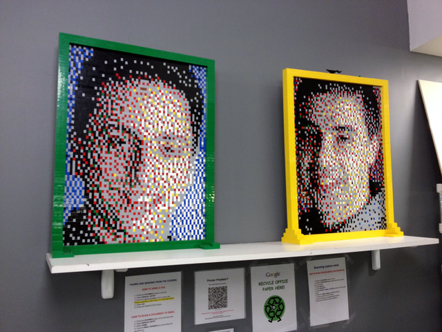
The review that I will be doing today would be based entirely on the NXT-G blocks that have been provided by Dexter Industries. In the photo above, I have both the dGPS module writting the to the NXT display, while on the right, I have HTC Desire with a GPS app, obtaining it the current location coordinates. If you are able to look closely, both of them are actually giving out different coordinates... of by a few decimal points.

View GPS for the LEGO Mindstorms NXT in a larger map

I have plotted both the coordinates on Google Maps. As you can see, both shows a different location, about 10 feet apart. Which one is more accurate? Well both is off by a little, as in one if off to the right, while the other is off to the left. I would need to check this with a few more location to determine which is the most accurate.

In the same map, I have also plotted a path that takes me around the KT town area. The path is marked in red. I have also attached the NXT-G files used to log the data, as well as a KML Path Creator at the end of this post.


You'll have to download 2 custom NXT-G Blocks available here. One you have downloaded and added it into your NXT-G software, you'll be to use it under the Advanced tab.

The first Block is the GPSRead, where it is able to extract all the information from your new dGPS module to your NXT. You could either write it to your NXT Display or even a text file on your NXT.

I have modified one of the sample codes to both display the information on the screen as well as write it to a file. When you write the coordinates to a file, with fixed interval, you'll be able to plot a path, as shown in the Google Map above (red path).


The next Block available is the NXTNavigation block. Given a destination coordinates, it will return the distance and angle to the destination from the current location. The usage is a little different from the GPSRead block, but it has it own purpose.

Overall the dGPS module is excellent. To log on to the satellites is pretty quick on a clear open sky (less than a minute), but takes up to a few minutes if it is very cloudy. The response that I am able to get, even at 1 second interval is acceptable.

I'll have to do more advance vehicle or robots to fully utilize the dGPS module's full potential.

Resources:
Download and view PDF Instructions on how to Collect and Upload data to Google Maps.
Download the NXT-G file for data logging here.
Download KML Path generator here.


Wednesday, 24 August 2011

dGPS Preview (Dexter Industries Sensor)

I have just received the dGPS that is made by Dexter Industries.

I have been playing over the last few days. I have been using it to collect information, that I later convert and upload directly to Google Maps

Attached here is a Google Map with me driving around the town where I stay. Used the sample codes available at Building Blocks (taken from Dexter Industries resource/downloads) and have modified it a little.

I will continue to modify the NXT-G codes, making it easier to use. Before uploading the finished NXT-G codes here.

I  am also in the middle of editing a special Excel file that will auto generate the KML file used by Google Maps. Easier to manipulate the data for upload.

I will do a full review over the next few days, completing the NXT-G codes as well as any other files created.

Stay tuned!!

Sunday, 7 August 2011

Moonbots 2011 - Prototyping & Robot Design

What I love about LEGO is that, given similar (or even same) parts, the possibility to create something seems to be infinite. So many possible solution for the same task...

The following is more of a Photo blog, of our attempt to prototype and design a vehicle for our Moonbot mission.

We started off with trying 2 basic design
  • Tank Track based, with 2 driving motor.
  • Car Based (4 wheel) with a front steering system.

 A very quick tank track based prototype done. After a few runs over the Moonbot ridges I have deem this design a little too unstable. It couldn't get over the ridge consistently, most of the time either falling on its back before going over, or falling head first after it has gone over the ridge.

 This was one of the first car based prototype that the kids had produced for me. It worked fine and was able to traverse any flat terrain properly. However the turning circle was bad.... really bad. With this design, we too had difficulty crossing the ridge, as it is tail heavy (note the NXT is behind the back drive wheel). Told the kids to move the NXT to between the 2 drive axle, giving it better balance.


The front steering wheel mechanism is really simple (anyone knows the name of this design?). It is just motor connected directly to the steering arm. No rocket science. Simple and effective.... However this design does have a tiny flaw.... it is difficult to get a good turning accuracy, as well as the terrain and ridges sometimes pushes it out of alignment.

The driving motor is connected to the drive axle directly. This design is able to push maximum power without any gears (speed or torque design). Simple and effective. However the trade off for this design is that it doesn't allow the car to turn properly (inner wheel is slower than other wheel).

We did a redesign it and tried it with a differential drive train. It worked very well when the vehicle is on flat terrain and when it is turning. However when faced with uneven terrain as well as Moonbot ridges, sometimes when all traction was lost to 1 wheel, thus transferring all the energy to the other wheel, causing inadequate traction and power to cross the ridge.

I reckon if we could try a limited slip differential, it could work. However with complicated design, it also could mean that the vehicle could be more unreliable. We decided not to try that design and just stick with the simple design and work within the limitations.

Here is a photo of another design of our tank track based vehicle. The student added some gearing, for it to power all the drive wheels, as well as added some counter balance to the robot. It did have great torque and was able to climb over the ridge easily, however the balance was difficult to overcome, causing the vehicle to constantly fall over the ridge.

While the some of us were killing our brain cells trying to figure out the best possible design for our vehicle, other students had the opportunity to do research and prepare for their STEM out reach project. The STEM out reach is worth a whopping 40% of the total, so getting this done properly was essential to the overall score

Alright... moon moon moon.... what else do I need to know about the moon.... Google this Google that.......

We decided to add a torque (speed down) gearing to the front drive arm. This makes the turning a little more accurate (but slow reaction), at the same time making it harder for the drive arm to mis-align when it hits the ridge or the uneven terrain.

One of our first working prototype with the NXT Brain moved to the centre for better balance and a new rake style arm for grabbing the objects. We experimented with this design. It was able to move over the ridge quite consistently, however the heading direction wasn't that consistent due to the uneven ridges pushing (mis-aligning) the vehicle steering arm.

Here is another prototype of a long reach rake style arm for trying to grab the objects from a further distance. The idea is NOT to go into Cravin Crater as it would be near impossible to leave it when you are within it.

Overall over the 2 days that I spent with the kids, it was great. We had many brain storm sessions, prototyping most of the designs we wanted to try and then decided which was the one that should be used. It was good as it wasn't my duty to dictate which is the best direction of building the best vehicle but give the opportunity to the kids to prototype, trial and decide.

LEGO Minifig on NASA Jupiter Mission


NASA's Jupiter-bound Juno spacecraft will carry the 1.5-inch likeness of Galileo Galilei, the Roman god Jupiter and his wife Juno to Jupiter when the spacecraft launches this Friday, Aug. 5. The inclusion of the three mini-statues, or figurines, is part of a joint outreach and educational program developed as part of the partnership between NASA and the LEGO Group to inspire children to explore science, technology, engineering and mathematics.

In Greek and Roman mythology, Jupiter drew a veil of clouds around himself to hide his mischief. From Mount Olympus, Juno was able to peer through the clouds and reveal Jupiter's true nature. Juno holds a magnifying glass to signify her search for the truth, while her husband holds a lightning bolt. The third LEGO crew member is Galileo Galilei, who made several important discoveries about Jupiter, including the four largest satellites of Jupiter (named the Galilean moons in his honor). Of course, the miniature Galileo has his telescope with him on the journey.

The launch period for Juno opens Aug. 5 and extends through Aug. 26. For an Aug. 5 liftoff, the launch window opens at 8:34 a.m. PDT (11:34 a.m. EDT) and remains open through 9:43 a.m. PDT (12:43 p.m. EDT). The spacecraft is expected to arrive at Jupiter in 2016. The mission will investigate the gas giant's origins, structure, atmosphere and magnetosphere. Juno's color camera will provide close-up images of Jupiter, including the first detailed glimpse of the planet's poles.

NASA's Jet Propulsion Laboratory, Pasadena, Calif., manages the Juno mission for the principal investigator, Scott Bolton, of Southwest Research Institute in San Antonio. The Juno mission is part of the New Frontiers Program managed at NASA's Marshall Space Flight Center in Huntsville, Ala. Lockheed Martin Space Systems, Denver, built the spacecraft. Launch management for the mission is the responsibility of NASA's Launch Services Program at the Kennedy Space Center in Florida. JPL is a division of the California Institute of Technology in Pasadena.


Ref: http://www.nasa.gov/mission_pages/juno/news/lego20110803.html

Saturday, 30 July 2011

Moonbots 2011 Playfield & Mission

I was invited over to give the Techno Inventors a hand in the Phase 2 of their Moonbots 2011 competition. Below is the overall playfield.


It is actually very huge,  with 5 x 5 large lego plates as the base! The whole playfield is huge, with the walls at the back with Earth as the background was really cool. There is a landing pad which is black in colour situated at the left side of the photo.


These are 4 of these (Black & Orange) object to pickup from the field. It is called Helium-3 and worth 15 points each. Please note the 4 brick high wall ridges that the vehicle would have to traverse to get to the other side of the play field!


This is a photo taken low within the Crater Canvin. Please note that it has been filed with 2000 orange 1x1 bricks making it rather impossible for a vehicle to traverse into this crater, let alone get out of it, specially when it is surrounded with a 4 brick high ridge!!?? There are also 4 Water Ice element (White & Blue) object to collect while in here. Each is worth only 10 points. Please note the backgrouns has the red marking and some plus signs.... it is known as the Heritage Artifacts. Capturing a image of it will grant you 20 points!

Here are the breakdown of the points on the Playfield (350 points total)
  • Lander Dismount (leaving the base/landing site) - [20 points]
  • Discover Water Ice (pick up Blue & White objects) - [10 points x 6 units]
  • Survive the Lunar Night (Stay on top of the Peak of Eternal Light for 5 second) - [30 points] 
  • Discover Helium 3 (pickup up Black & Orange objects) - [15 points x 4 units]
  • Capture Mission Video (video the entire run of the mission) - [20 points]
  • Photography the Heritage Artifacts (video the Heritage Artifacts) - [20 points]
  • Return to Base (touch the base) - [20 points]
  • Return Elements to base - [x2 points of each element]
  • Touch Penalty - [minus 50 points each time]

Opinion and Play difficulty of the Moonbots 2011
  • Playfield is build with Lego Plates. Surface is studed making the movement of the vehicle inaccurate
  • Ridge is at least 4 bricks high, make it difficult for the vehicle to traverse over it
  • Crater Cravin is filled with 2000 pieces of 1x1 bricks making it almost impossible to be moving accurately within the crater. 
  • Getting out of the crater would also be impossible as there is no traction on the wheels.
  • As all the elements are very similar, designing only 1 arm to collect/pick up the elements is required
Overall, it is no easy mission. Compared to FLL or NRC it has its own challenges. Please note that there is only about 6 weeks time provided to complete the mission as well as the other activities as per the Moonbots requirements.

Total scoring for Phase 2 is as follows
  • Blogging requirement met (5% weighting)
  • Robot design proposal turned in on time and the design matches the robot construction (15% weighting)
  • Creativity and technical merit of STEM Outreach project (40% weighting)
  • The Science Mission Score achieved during the Live Mission Webcast (40% weighting)

Wednesday, 6 July 2011

Techno Inventors of Sekolah Seri Cahaya is Moonbots Finalist!

We would like to congratulate Techno Inventors of making it to the finals of Moonbots. For those who haven't heard of the competition, you could head to moonbots.org for more info.

To see the top 20 finalist, you can click here.

Better still, click here to view their team websit.

Malaysia is 1 of the 2 non-US teams in the 20 finalist teams. The other one is from Chile.

Check out their Video selection below that allowed them to make it to the finals!


The oldest student is only 13 years old and the script was done mostly by the kids. I guess the humor element made them stand out.

Once again, congratulations on making it to the top 20.

Friday, 15 April 2011

Line Follower Algorithm - Which is the best?


Single Light Sensor - Bit logic method (1 Min 59 Sec)
Read full post here.


Single Light Sensor - PID method - Smooth (1 Min 29 Sec)
Read full post here.


Single Light Sensor - PID method - Over Correction (53 Sec)
Read full post here.


Dual Light Sensor - PID method - Smooth and Fast (33 Sec)
I have not posted about this Line follower that I had built. It moves really fast and because there is 2 light sensors, it is able to adjust and move along quickly. I am trying to optimize the dual sensor to go even faster. Will post the outcome when I am done.

Line Follower - PID Method - Over corrected!


This post is a followup to the previous PID Line Follower post, of which I was using the PID method. As you would have noticed in the previous post, the Line follower robot was moving very smoothly over the black line, however it was extremely slow!

Please note that the line follower robot is only using 1 light sensor, the left one. The robot has been built with 2 sensors for future test algorithm.

In this followup post, you'll notice that the robot moves along at faster rate, but the robot seems to be constantly oscillating, with a few occasion that it manage to reach equilibrium. This is because the robot seems to be over compensating. The reason that this could happen is because is because the robot's feedback loop is too slow to react, and is NOT able to compensate quick enough, causing it to go into an oscillation mode. I would have to re-code the robot using NXC or RobotC to overcome the speed issue.

Another possibility is because of the variables that I have used to adjust the robot for a faster speed, rather than a smooth moving robot. Maybe the setup variables is inaccurate, thus the robot is unable to hit its equilibrium. However in the video above, the robot did reach an equilibrium state (moving straight) occasionally.

I will post the source codes in the future post after I have done investigation on how to make the robot move faster yet smoother.

If anyone has manage to complete the above task, please post in the comments how you manage to make the robot move fast yet smooth with 1 light sensor.

Line Follower - PID Method - Smooth


I hope most of you have read the Bit Logic line follower algorithm. Next I will explore the PID method, which I have been reading alot lately on the Internet. I reckon, for most high school students understanding just the "theory" of PID will be enough to put you through college :p

Please note that the line follower robot is only using 1 light sensor, the left one. The robot has been built with 2 sensors for future test algorithm.

Anyway, if you would like a very detailed theory, calculations and formula for the PID method, please follow this link.


If you have watched the video, you would realised that the robot tries to correct itself to stay in the middle, between the black and white areas, as shown in the image above. After a few oscillation, it would be moving along the grey area (between the white and black).


The graph above shows the Motor power output vs the readings from the Light sensor. As you can see, the robot will always try to keep within the Grey area (dotted line B), which is the equilibrium. When the Left motor and Right motor, is travelling at the same speed, the robot is actually move straight.

When the Light sensor is above the White area (dotted line A), you'll notice that the Right motor will stop, while the Left motor is moving at full power, causing the robot to turn right, thus heading towards the Black line.

When the Light sensor is above the Black area (dotted line C), the Left motor will stop, while the Right motor is moving at full power, causing the robot to turn left, thus heading towards the White area.

As you can see, since the graph is linear, the robot should automatically correct itself till it is moving along on its equilibrium (dotted line B), as you can see in the video attached above.

Saturday, 9 April 2011

Line Follower - Bit Logic Method


I have been tasked to teach one of the most fundamental programming ideas, Line Follower.

Before we begin, we should understand what Line Follower algorithm there is, and what is the best and quickest method. So today we will explore the easiest one of them all, the 2 bit line follower algorithm.


View the image above, the Black Box represents an enlarged Black line, while the tiny Red line represents where the light sensor is on and what it will see. You will notice from the video above, you will notice that the NXT Mindstorms actually makes very tiny zig-zag along the black line. If you look closely, it is actually like the red line above.

The idea is simple, if the sensor is over White (Point 1), you turn right towards the Black area. When you are over the Black (Point 2), you turn left towards the White area. Effectively you are hugging the left edge of the Black line.


Using just the a simple Switch Block, and 2 Move Blocks, we are able to program the bit logic line follower, as explained in the previous paragraph.

Being the easiest line follower algorithm to understand and teach doesn't make it the fastest. It only manage to complete the track in about 2 minutes, which is extremely slow!